Creating a Programmer's Clock with Arduino and Hexadecimal Display
Have you ever wanted a clock that speaks the language of programmers? Imagine a clock where the time is not in the typical digits but is represented in the hexadecimal format familiar to those who delve into the world of coding. In this post, I’ll share my journey of creating just that – a Programmer’s Clock.
The Inspiration
As a programming enthusiast, I’ve always been fascinated by hexadecimal notation. It’s the base-16 numbering system that programmers frequently encounter in their coding adventures. So, the idea of a clock displaying time in hexadecimal was born.
The Components
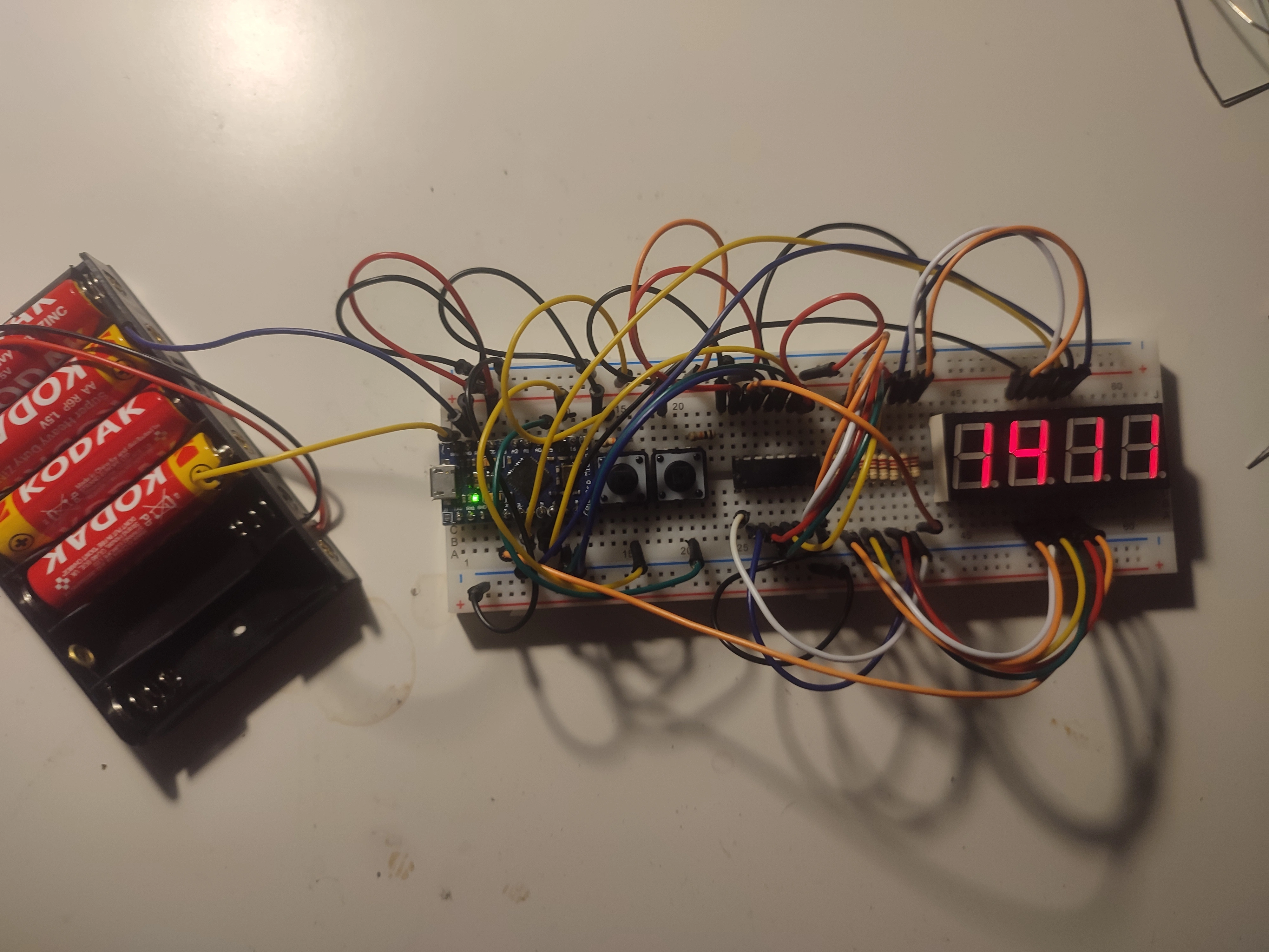
To bring this idea to life, I gathered the following components:
- Arduino (I used an Arduino Leonardo clone)
- 4-digit 7-segment display
- 2 buttons for setting hours and minutes
- 10 resistors
- 74HC595 shift register
The Schematic
The schematic below shows how the components are connected to the Arduino. The 7-segment display is controlled by the shift register, which is connected to the Arduino via the SPI interface. The buttons are connected to the Arduino’s digital pins, and the resistors are used to limit the current flowing through the 7-segment display.

The Code
#include "SevSegShift.h"

#define SHIFT_PIN_DS 8   /* Data input PIN */
#define SHIFT_PIN_STCP 7 /* Shift Register Storage PIN */
#define SHIFT_PIN_SHCP 6 /* Shift Register Shift PIN */

#define BUTTON_LEFT_PIN 14
#define BUTTON_RIGHT_PIN 15

int timeOffset = 0;

struct time
{
  unsigned long long milli;
  unsigned long long seconds;
  unsigned int minutes;
  unsigned int hours;

  void getTime()
  {
    unsigned long long currentTime = millis();
    long long adjustedMillis = currentTime % 86400000 + timeOffset * 60000;

    // Ensure that adjustedMillis is positive
    if (adjustedMillis < 0)
    {
      adjustedMillis += 86400000;
    }

    milli = adjustedMillis;
    seconds = milli / 1000;
    minutes = seconds / 60;
    hours = minutes / 60;
  }
};

time clock;

unsigned long buttonPressStartTime = 0;
const unsigned long holdThreshold = 100;        // Time in milliseconds to consider a button press as "held"
const unsigned long initialIncrementDelay = 50; // Initial delay between increments in milliseconds

enum ButtonState
{
  IDLE,
  PRESSED,
  HELD
};

ButtonState leftButtonState = IDLE;
ButtonState rightButtonState = IDLE;

// Instantiate a seven segment controller object (with Shift Register functionality)
SevSegShift sevseg(
    SHIFT_PIN_DS,
    SHIFT_PIN_SHCP,
    SHIFT_PIN_STCP,
    1,   /* number of shift registers there is only 1 Shiftregister
            used for all Segments (digits are on Controller)
            default value = 2 (see SevSegShift example)
            */
    true /* Digits are connected to Arduino directly
            default value = false (see SevSegShift example)
          */
);

void setup()
{
  byte numDigits = 4;
  byte digitPins[] = {5, 4, 3, 2};               // These are the PINS of the ** Arduino **
  byte segmentPins[] = {0, 1, 2, 3, 4, 5, 6, 7}; // these are the PINs of the ** Shift register **
  bool resistorsOnSegments = false;              // 'false' means resistors are on digit pins
  byte hardwareConfig = COMMON_ANODE;            // See README.md for options
  bool updateWithDelays = false;                 // Default 'false' is Recommended
  bool leadingZeros = true;                      // Use 'true' if you'd like to keep the leading zeros
  bool disableDecPoint = false;                  // Use 'true' if your decimal point doesn't exist or isn't connected. Then, you only need to specify 7 segmentPins[]

  sevseg.begin(hardwareConfig, numDigits, digitPins, segmentPins, resistorsOnSegments,
               updateWithDelays, leadingZeros, disableDecPoint);
  sevseg.setBrightness(100);

  Serial.begin(9600);
}

void checkButton()
{
  int leftButtonStateNow = digitalRead(BUTTON_LEFT_PIN);
  int rightButtonStateNow = digitalRead(BUTTON_RIGHT_PIN);

  handleButton(BUTTON_LEFT_PIN, leftButtonStateNow, leftButtonState);
  handleButton(BUTTON_RIGHT_PIN, rightButtonStateNow, rightButtonState);
}

void handleButton(int buttonPin, int buttonStateNow, ButtonState &buttonState)
{
  if (buttonStateNow == HIGH)
  {
    if (buttonState == IDLE)
    {
      // Button pressed for the first time
      buttonState = PRESSED;
      buttonPressStartTime = millis();
      timeOffset += (buttonPin == BUTTON_LEFT_PIN) ? -1 : 1; // Adjust timeOffset
    }
    else if (buttonState == PRESSED)
    {
      // Button held down
      unsigned long elapsedTime = millis() - buttonPressStartTime;
      if (elapsedTime >= holdThreshold)
      {
        buttonState = HELD;
        buttonPressStartTime = millis();
      }
    }
    else if (buttonState == HELD)
    {
      // Increment timeOffset and adjust delay
      unsigned long elapsedTime = millis() - buttonPressStartTime;
      if (elapsedTime >= initialIncrementDelay)
      {
        timeOffset += (buttonPin == BUTTON_LEFT_PIN) ? -1 : 1;
        buttonPressStartTime = millis();
      }
    }
  }
  else
  {
    // Button released or not pressed
    if (buttonState == PRESSED)
    {
      // Reset button press start time when button is released after a short press
      buttonState = IDLE;
      buttonPressStartTime = 0;
    }
    else if (buttonState == HELD)
    {
      // Reset button state when button is released after being held
      buttonState = IDLE;
      buttonPressStartTime = 0;
      // Additional actions can be added here for the end of held state
    }
  }
}

void loop()
{
  checkButton();

  clock.getTime();

  int displayTime = ((clock.hours % 24) << 8) | (clock.minutes % 60);
  Serial.println(displayTime);
  sevseg.setNumber(displayTime, -1, true);
  sevseg.refreshDisplay();
}
Writing the code for the clock involved converting the current time into hexadecimal format and updating the display accordingly. The buttons allowed for easy adjustment of the hours and minutes. The 74HC595 shift register efficiently controlled the 7-segment display, making the code both elegant and functional.
Testing and Debugging
No project is complete without its fair share of testing and debugging. I meticulously went through each function, ensuring that the clock displayed the correct time in hexadecimal format and that the buttons worked seamlessly for adjusting the time. Debugging is a crucial part of any programming project, and it’s where the real learning happens.
The Final Product
After overcoming challenges and refining the code, I was able to witness the successful creation of my Programmer’s Clock. The 4-digit 7-segment display now showcased the current time in hexadecimal, providing a unique and visually appealing twist to the conventional clock. The user can change the time using 2 buttons. Pressing the button will adjust the time by 1 and holding it will quickly increase or decrease the time.
Conclusion
Creating a Programmer’s Clock was not just about displaying time differently; it was a journey of combining programming skills with electronics. The integration of the Arduino, 7-segment display, buttons, resistors, and the shift register resulted in a tangible, functional piece that speaks directly to the hearts of programmers.
Whether you’re a seasoned coder or a hobbyist, experimenting with Arduino and electronics can be a rewarding experience. It opens up a realm of possibilities for creative projects that blend coding and hardware. So, if you’re feeling inspired, gather your components, write some code, and embark on your own journey of crafting something uniquely yours.